Low Profile,
Aluminum Downspout, Solar Hot Air Construction Project
What follows is our low profile, solar hot air collector project built using aluminum downspouts. Farther down the page you'll find a much larger version that another Scott (Scott S.) built based on our original design, but with some great enhancements!
Scott
& Brad's Original Design
Then others followed with bigger aluminum downspout collectors that have some nice design enhancements:
Scott
Smith in New York's Enhanced Aluminum Downspout Version
Dick
in Ohio's
Very Attractive Downspout Collector
Jeremy
in WV built this 24' X 4' downspout collector behind his deck
My son Bradley and I love to brainstorm
solar project ideas! It's good for the environment, saves
money and most of all, it is a lot of fun as a father and son
activity. I have virtually no carpentry experience, so
anything that we take on has to be easy to build. The
only power tools that we used were a drill and jig saw. We
also wanted to come up with an inexpensive, functional design
with parts readily available at the local hardware store or
ordered on line.
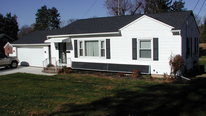
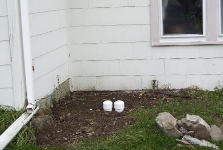
Our design also has to be neighborhood friendly. South faces towards the street, but by keeping our project low to the ground and with some low shrubbery in front, our hot air solar collector can be well hidden. What we came up with is a design that wound up being only 13 inches high by 24 feet long. Here are the construction details:
Parts (collector only - all available at our local Lowes hardware store):
5, 10 foot pieces of 3"
X 4" aluminum down spout
12, 1" X 6" X 8' pressure
treated lumber
2, 1" X 4" X 8' pressure treated lumber
1
section 4" PVC drain pipe (thin, schedule 80)
2, 4"
PVC 90 degree angles
2, 4" PVC to 3" X 4" aluminum
down spout adapters
Foam insulation
Outdoor wood screws
Flat black spray paint
Caulk
6
Pieces of 12" X 48" UV stabilized Plexiglass (ordered
online from www.usplastics.com)
Construction:
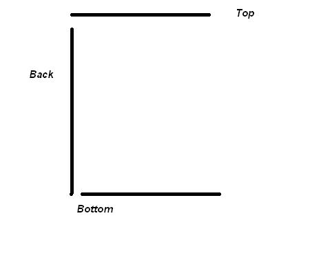
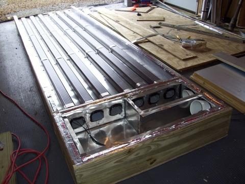
We began by laying out the project in the garage. The back is laying on the floor with the bottom to the left. I cut one of the 1 X 6 pieces in half so that the pieces would be staggered. They were connected using 11" pieces of 1 X 4s (not shown).
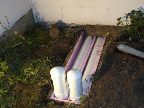
Here is a better look at the inlets. They are simply 90 degree angles and 4" PVC to 3" X 4" down spout adapters connected by a small section of PVC.
To make the turn in tight
quarters, we cut openings in a small section of 4" PVC with
a jig saw and capped both ends:
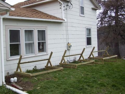
So that everything fits, place your screws through the back into the bottom and then through the top into the back. This results in the bottom being 7 inches wide and the top being 6 inches wide:
The frame sits nicely on our window wells:
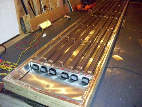
We added some foam insulation
to the back. Then aluminum downspouts were
caulked and inserted. A couple pieces of insulation were used
to keep the downspouts from resting on the bottom and to separate
the two downspouts:
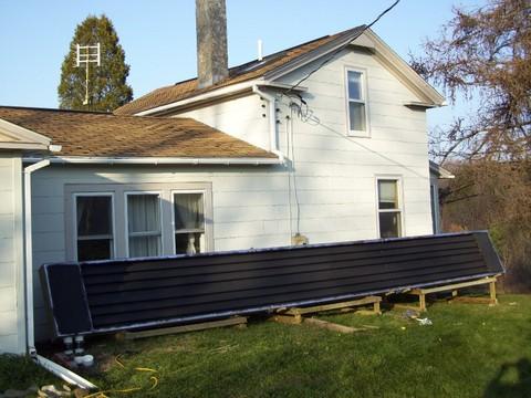
We painted the assembly with flat black spray paint and then covered it with Plexiglass, The Plexiglass rests against the top and bottom boards. Also, every 4 feet there is a 1" X 2" (a 1" X 4" cut in half longways) in front of the downspouts that the Plexiglass rests against:
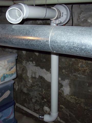
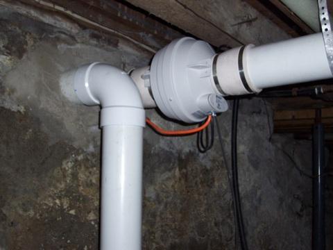
Inside the basement (parts used inside not listed above). Our theory is that we will pull cold air off the basement floor. The warmer air returning will rise and warm the house throughout the sunny day. The basement effectively becomes the thermal storage area. The fan is switched on and off by a Delta - T, DTT-94 thermal differential sensor (a cheaper alternative is to use a snap switch that turns on at 100 degrees and off at 80 degrees. They are only about $10.). Warm air exits the PVC T below the fan. The PVC section below the T is simply to support the Fantech HP2190 (163 cubic feet per minute) fan (I understand that squirrel cage fans are less expensive).
How does it work? What follows are readings as we progress into winter:
Completion date - September, 2008. We just finished the project yesterday. We were able to raise the 75 degree inlet temperature to the mid 130s and briefly over 158 degrees (the max my digital thermometer reads) where it exits the outlet, with sunshine and a 79 degree outside temperature. I'll update this page when I get better data, but early results are exciting!
Update - October. With the outside temperature in the mid 50s, the collector is able to take 68 degree inlet temperature and consistently output 116 degrees at approximately 80 cubic feet per minute through the mid day hours. We will see how well it works when it is 20 degrees colder, but I'm very pleased so far.
Update - November 29th. An outside temperature of 46 degrees, an input temperature of 59 degrees and a sustained midday output of 107 degrees at 80 CFM. Assuming 280 BTUs per square foot, that works out to an efficiency of 62%! I understand that a 50% efficiency rating is typical for solar collectors.
Update - December 13th. We are within a week of the solar minimum, an outside temperature of 35 degrees, an input temperature of 61.7 degrees and a midday output of 101.8 degrees at 80 CFM. Assuming 263 BTUs per square foot, that works out to an efficiency of 55%! I am thrilled and consider this project a complete success!
I'm very happy with the performance numbers, but another great measure of success occurred in mid October. My wife had been tolerant of my solar experiments, but I sensed she was not exactly on board. When I got home from work one day during a particularly chilly week, completely unprompted, my wife enthusiastically told me how impressed she was with the way the solar hot air collector was warming up the house. At that moment, I knew this project was a complete success! My 18 year old son said almost the same thing in early December, again without any prompting from me.
It is one thing to talk about
degree temperature rises and efficiency numbers, but you can't fully
appreciate the power and potential of solar until you feel for yourself
the thrill of that free hot air cranking out of your system, blowing
across your hands and warming up the room. Your friends will
be impressed too!
1. Use aluminum angles to secure the glazing instead of screws. The plexiglass tends to flex under heat and bows using screws creating air gaps. Angles hold the plexiglass to the frame while still allowing it to expand without bowing. I actually did replace the top but I couldn't get to the bottom without dismantling the unit. The 8' aluminum angle strips are only a couple bucks at HD.
2. I have insulation on the back, but I could have put some in the bottom and top. It's not a large area, but it all helps.
3. Build bigger! I could have made the collector 2 feet high and it still would have been well hidden and neighborhood friendly. That would have doubled my output with 50 square feet of collector area. Always build as big as you can. It is an investment that will pay for itself many times over.
4. Use SunTuf glazing (especially if I had made it two feet high). It is a cheaper option.
5. I like the convenience of the differential sensor and I'd probably do the same thing again, but for anyone who can easily run electric out to the collector, get a thermal snap switch for $10 and save about $150. The cost can also probably be reduced by using a squirrel cage fan.
Update (12/13/09) - This past fall I did replace the differential controller with a simple snap switch so that I could use the controller in another project. I used this snap switch, it only cost $6.75 and it is working fine: http://www.pexsupply.com/White-Rodgers-3F01-110-3-4-Snap-Disc-Fan-Control-Cut-In-110-Degrees-F-Cut-Out-90-Degrees-F-14691000-p
6. I don't have a better alternative for the right angle corners in a small space, but I think that there might be one.
Update, I received this excellent suggestion from Dave on the SimplySolar e-mail group (see below to subscribe). This approach would be easier to build and will provide better airflow:
There certainly is [a better
approach]. It's called a plenum. Basically a plenum, for this
instance, is merely a box with an inlet and an outlet.
There is some rule
of thumb that says that for every 90* turn in the pipe there is a large (this is
the part I forget) % loss in flow. 4 of these (2 at each end of your collector) can be
eliminated by extending your collector box about 1 foot on each end, boxed in
and sealed. Keep the ends of the downspouts so they are the inflow and
outflow. The extra volume in the box (considerably more than there is in the 4"
piece of pipe that you are currently using) makes for an almost unrestricted air
flow from one tube to the next.
Here's what you have now, which is a 180*
turn (i.e. 2ea 90* turns).
______
|
|_____________________
| <----
downspout
| _____________________
|
|_____________________
| ----> downspout
| _____________________
|______|
What you need is
something similar, only at least double the volume.
Hence:
_____________
|
|_____________________
| <----
downspout
|
_____________________
|
|_____________________
| ---->
downspout
|
_____________________
|____________|
It's probably simpler
than you thought.
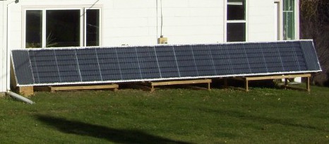
Enhanced Downspout Hot Air Collector Design by Scott S.
Scott S. took our basic design and made some great enhancements including:
-
Building much bigger - 32.5 feet long by 3 feet high for 97.5
square feet of collector area
- Built with a 64 degree
tilt angle to maximize the winter sun in January and February
-
Used plenums (described above and pictured below) for better air flow
-
Built so that the collector can be stored indoors during the summer months
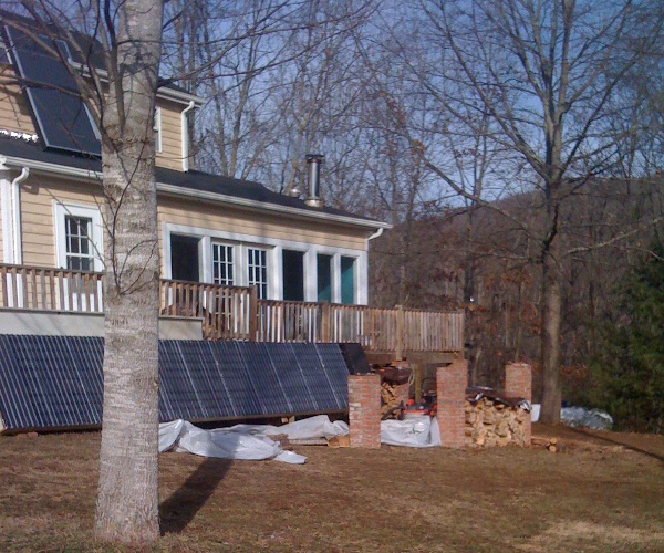
Here are the pictures for Scott's project:
Air
tubes capped off for summer
Air
tubes
Intake
air plenum (excellent design for good air flow!)
End
plenum
Stands
Collector
before glazing
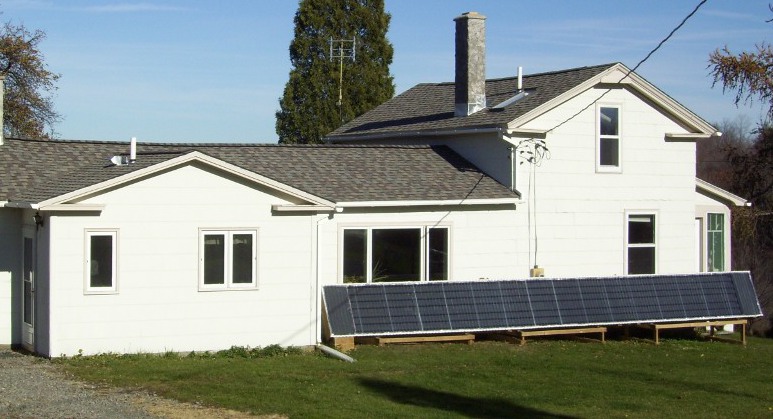
Finished!
Interior
ducting and fan
Scott
originally used one fan, but the collector was
cranking out so
much heat, more than 150F....
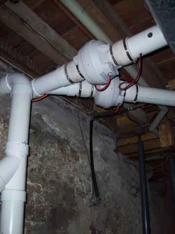
So
he added a second fan!
The scheme is brilliant. The snap switch for the second fan is actually on the output of the first fan and is set higher than the snap switch inside the collector. On partly cloudy conditions when the collector isn't as hot, only one fan runs.
Scott is seeing super performance from his panel! Here is a report from Scott that was done on December 12th, within 8 days of the solar minimum:
The collector came to life at 8:15 am. Outside air temperature was 13°. I decided to see what would happen if I didn't put any wood on the fire this morning, and just used solar only for a while. The inside temp dropped about a degree from the initial 67°, but by 10am we were increasing. Our high today was around 31°, and we stayed a comfortable 68° with no other heat source than the collector. Pretty cool...I finally made a fire in the wood stove around 3 pm to keep from cooling off as the sun dropped. The collector finally shut down at 3:30 pm.Scott S sent his revised efficiency numbers along recently, but since I've been referring to his previous numbers so often, I want to make sure that no one misses the correction. His previous calculations showed an efficiency topping out at 62% with two fans running and an output of 149F. In hindsight, that does seem quite incredible!
Below are Scott's revised numbers, showing an efficiency topping out at 43% with two fans running and an output of 149F. With an output temperature that high, 43% is a very respectable number.
Note that with one fan, the output temp is 155F and 36% efficiency. So, while the line won't be linear, at those high temperatures, each increase in airflow causing a one degree drop in output temperature results in more than one percentage point increase in efficiency!
155F - 149F = 6F temperature drop
43% - 36% = 7% efficiency increase
Again, the curve isn't linear, so a volume of airflow that would get his output temp down to 119F wouldn't necessarily get his efficiency to 73% (149F - 119F = 30F; 43% + 30 = 73%), but I suspect Scott could definitely see efficiency in the mid 50s to low 60s with increased airflow.
Here is Scott's revised data:

Thanks for checking out the
aluminum downspout hot air collector projects! If you have an interest in brainstorming
solar hot air projects that are easy and inexpensive to build and
neighborhood friendly, or want some help with a project you have
underway, I have set up an e-mail group - SimplySolar for that purpose.
You are very welcome to subscribe. Both Scott S. and
I are active participants on the group, so if you have questions
about our aluminum downspout collectors, this is the place to ask!:
SimplySolar - Solar Forum and E-mail Groups!
I originally set up an e-mail group - SimplySolar, for that purpose. The e-mail group has served us well, but with overwhelming growth and interest in the e-mail group, to better keep content organized and give members the option to easily follow only the threads that interest them, we have just set up a new Simply Solar on line forum! SimplySolar is about brainstorming and sharing ways to implement solar heat in easy ways that the average homeowner, who may not be much of a "do-it-yourselfer" (like me), can use to put money back in their pockets, green back in the environment and have a lot of fun along the way! If solar excites you, we would love to have you join our forum:
Click to visit or join the Simply Solar Forum
or subscribe to our e-mail group!
Thanks again!
Sincerely,
Scott Davis
![]()