
Loops - Nested or Stand Alone, are Super Antennas!
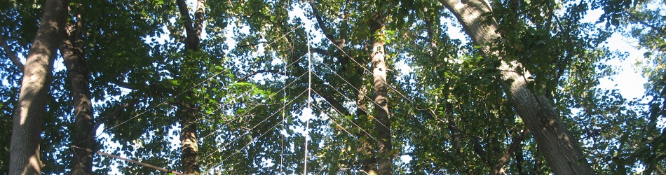
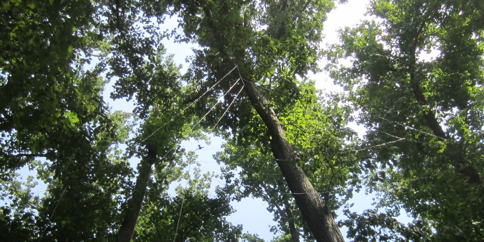
The top of the 5 band nested loop. The only time it is visible is for a few moments at sunrise. PVC not yet painted brown.
Here is a six minute video that details the dipole and loop antennas that netted us DXCC and WAS in 9 days with 100 watts! The antennas are a bit difficult to see in the video, but that underscores how stealthy they really are!
Full wave wire loops are an excellent antenna choice. This page summarizes two loop designs. The first expands on an article I wrote for QST that was published in their March, 2014 edition (page 40), posted here with permission. The second is an alternate approach to nesting loops that I've used more recently that completely eliminates the need for using PVC entirely!
Loops don't have to be nested. You can build a single loop for one band and it will work every bit as well. I like to nest them to save space and utilize one overhead support for many antennas.
Nested Loop Antennas - 5 Band, 4 Sided with PVC Support
This project started with Field Day. For years our group always did well on 80 and 40 meters, but busting pileups or running frequencies on 20, 15 and 10 meters remained elusive. Year after year we tried a variety of wire antennas and even some low beams, but we never had the thrill of a Yagi at enough height to put us squarely in the game.
My on the air experience at home was much the same. I had a tribander, but to keep peace with my neighbors it was only 20 feet high. That just wasn't cutting it when it came time to run a frequency, bust a pile up in a contest or work coveted DX.
For years those bands were a challenge. Finally, several years ago, inspiration came out of the air, or more precisely over it. During one of our local 2 meter nets, Bill, K3KEI suggested I try a full wave loop antenna cut for a specific band. Bill built a three sided Delta Loop for 17 meters that worked great, so I had to give it a try.
I started out by building a full wave, square loop for 20 meters. The loop hangs from a corner of the square, so it is in the vertical plane. It is fed from the bottom corner so that it is horizontally polarized. I pulled the loop into the air, turned on the rig and instantly knew this design was a winner!
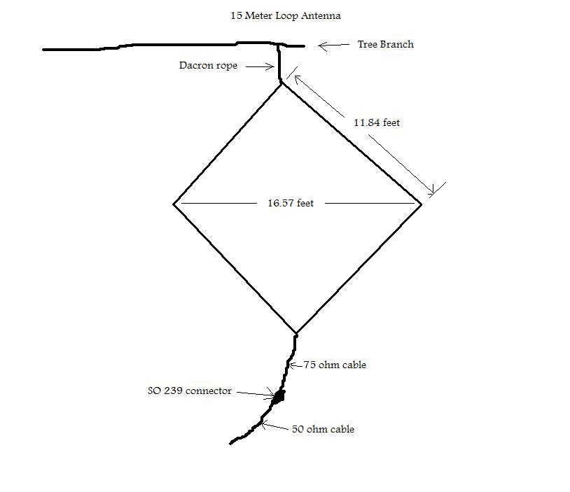
Concept drawing of the loop antenna. The dimensions shown here are for a 15 meter loop.
I fired up my Icom 756 Pro II, flipped my antenna switch from the beam to the loop and the rig’s spectrum display immediately popped up. My first loop contact from here in Maryland was with a station in Kansas, who gave me an S9 + 20 report with 100 watts! When I pointed my low altitude beam right at him and switched to it, my signal dropped to S9. Locally on ground wave, I also received a superior report with the loop. In both cases, the beam was pointed at the station being worked, but the loop beat it hands down!
For several years and many contests, my 20 meter loop antenna continued to work great! Even though I'm just running barefoot, I was able to hold my own in pile ups and often was able to run frequencies on that antenna! Until....
A beautiful, huge, falling white ash laid my original loop to rest. It was a big loss for my station's performance, so I vowed not only to replace it, but to build a nested loop array for 20, 17, 15, 12 and 10 meters. Five bands placed all within the same space that the 20 meter loop previously occupied. The supporting structure needed for 20 meters can easily accommodate the other bands too, so why not add more bands!
Construction of the 5 Band Nested Loop Array:
The loop can be built as a square or triangle. Since its performance improves as the interior area grows, I opted for a square, but three sided loops in a triangle shape work really well too. You'll find a 3 sided design that eliminates the need for using PVC entirely farther down the page.
The loop is hanging from the limb of a tree, so it is in the vertical plane, which may reduce ground losses compared to a dipole or horizontal loop. It is fed from the bottom corner, so that it is horizontally polarized for low noise.
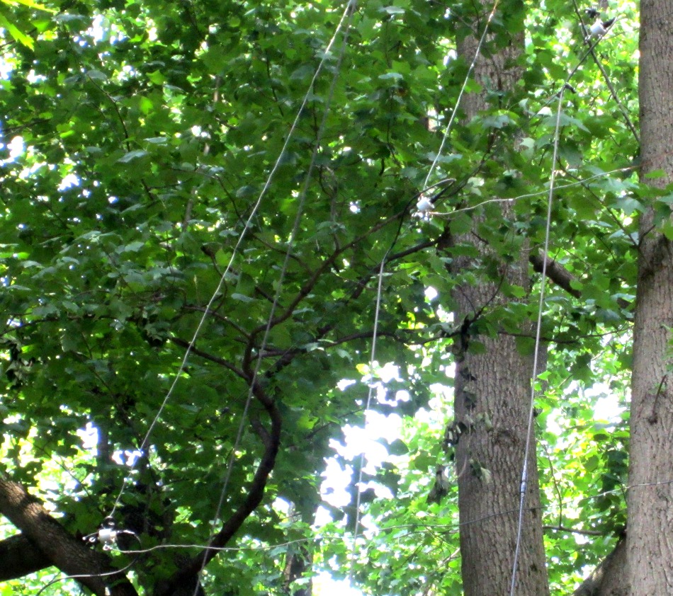
This antenna is well hidden and very neighborhood friendly! One of the best parts of hanging the antenna in the tree is that once you spray paint the PVC black or brown, it is virtually unnoticeable!
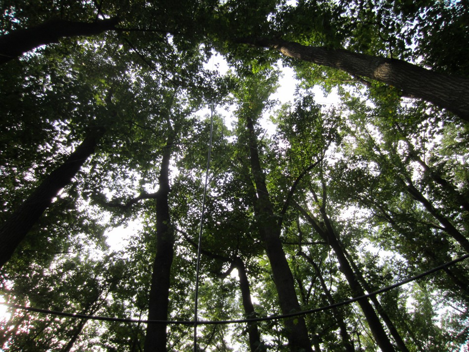
For most of the day the antenna is virtually invisible!
I used an EZ hang to run the Dacron line over the limb, but if you have a good arm, a baseball with a screw eye and fishing line tied to it is another option to get your line over your support.
I used 1/2" PVC and 1" X 2" pressure treated wood for supports (please see the section below on nested Delta Loops for an update on that). Had I only been building a single loop, I would have been tempted to forego the structure entirely and simply use the line at the top, coax at the bottom and a line at each corner to pull the loop into position (which is essentially what I wound up doing, in a later build, documented below).
I'm not sure where the source for these calculations originally came from, but here is how my son Brad, KB3MNE and I went about building our 5 band loop array this past summer. Example calculations are for the 15 meter element and I've included a table for sizing them all.
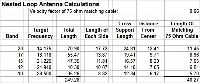
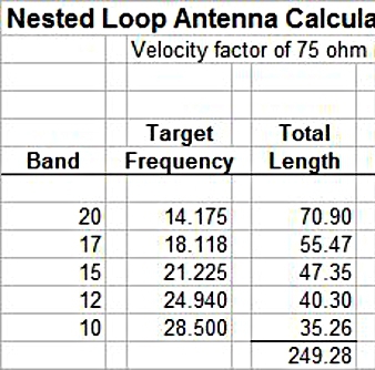
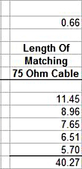
Here are all the calculations you’ll need for building your nested loop array.
Parts List (assuming you want all 5 bands):
Wire – 250 feet
75 ohm coax – 41 feet (RG11A/U or RG59B/U at thewireman.com)
5 CQ dipole center, SO239, center hang connectors (Part # 801 at thewireman.com)
5 double female, SO 239 connectors
10 PL 259 coax connectors
50 feet of ½” PVC (maybe try ¾” or telescope downwards?)
1 PVC, 4 way connector
4, PVC connectors
3, 1” X 2” X 8’s (if necessary)
Screws or PVC cement to secure PVC.
Dacron rope (Part # 816 at thewireman.com)
Steps (example calculations are for 15 meters):
1. Find the size of each loop by dividing 1005 by the frequency in MHz:
1005 / 21.225 = 47.35 feet for 15 meters. Go ahead and cut your wire.
2. Divide the length by 4 to determine the length of each side:
47.35 / 4 = 11.84 feet for 15 meters.
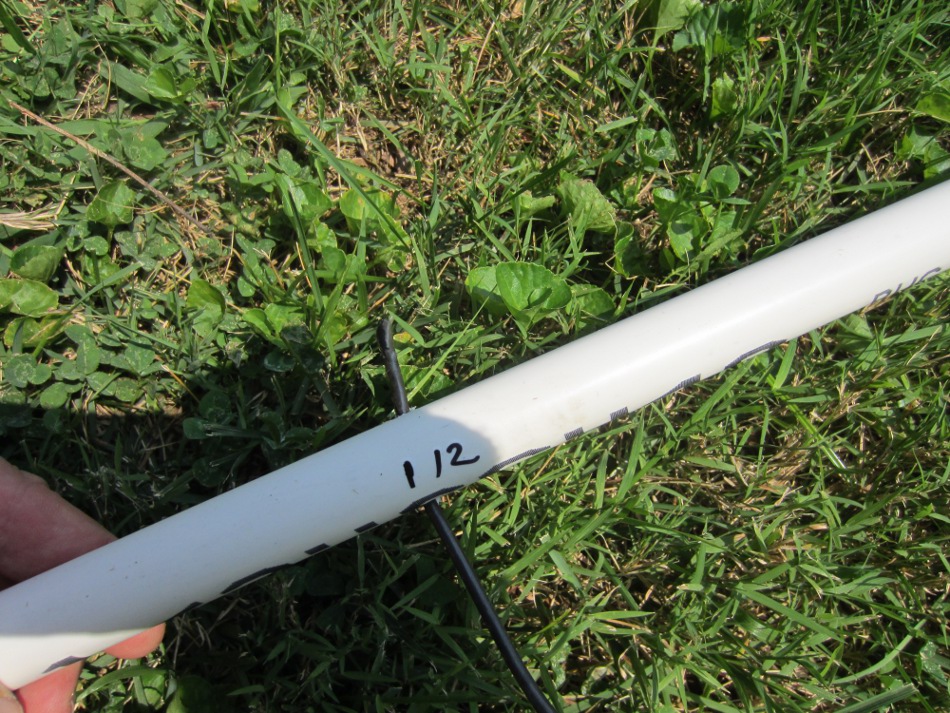
3. Since the PVC supports go to opposite corners, the supports must be longer than the sides. To determine the length, multiply by 1.4.
11.84 X 1.4 = 16.57 feet for 15 meters (length of PVC - corner to corner).
4. Assemble your PVC (I just used screws to hold the PVC together rather than gluing).
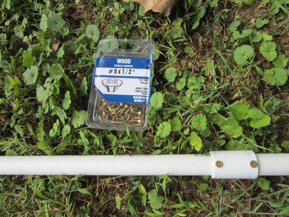
I just used screws to hold the PVC together rather than gluing.
5. Lay your wire out on the structure, temporarily taping it to find where it should pass through the PVC
6. Drill holes for the wire through the PVC. After you run the wire through, wrap a bit of electrical tape on both sides of the wire next to the PVC to keep the wire from sliding and to give the PVC additional support. When hanging, the wire actually supports the horizontal PVC piece and keeps it from drooping (It may bow though - see my notes below). For the bottom, rather than slide the wires through the PVC, I put screws into the PVC to hang the dipole connectors.
Sliding the 12 meter wire through the PVC.
7. A loop antenna is about 100 ohms, but don’t worry, with this next step, you’ll permanently convert it to a 50 ohm, broad banded antenna with very low SWR. Use a carefully cut piece of 75 ohm cable at a specific length for each band to tune your antenna for low SWR. Calculate the length for each band as follows: 492 / frequency in MHz / 2 X velocity factor.
492 / 21.225 / 2 * .66 = 7.65 feet of 75 ohm cable for 15 meters.
Just connect the 75 ohm cable coming from the antenna to your 50 ohm cable by a double female, SO 239 connector. With the matching cable in line, your SWR should be very low. No tuner needed!
8. Connect your matching length of 75 ohm coax to the antenna wire. You can either solder the shield to one side of the wire and the center to the other or use an SO 239 dipole connector. We opted for the SO 239 connector that Brad is pointing out with the antenna lowered here:
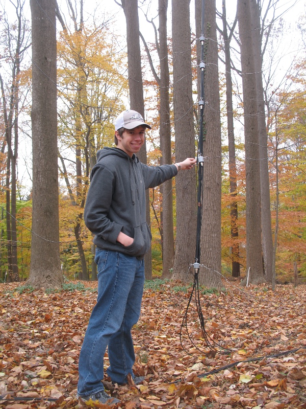
This was a great father and son project that Brad, KB3MNE and I really enjoyed!
Other notes:
The PVC is spaghetti on the ground, so build close to where you are going to fly your array. The structure is very light, but if you have to move it more than a few feet, you’ll need a helper to keep things under control. If you decide not to include 20 meters, it will be smaller and more manageable, but for me 20 meters is worth it!
When I first pulled the antenna into position, it had significant bowing of the horizontal PVC. Brad and I remedied that by taping some 1" X 2"s to the horizontal arms with Gorilla tape. This step was unnecessary when I built the single 20 meter antenna. (There is a second, better option below that doesn't use PVC at all!).
Each antenna element is completely independent of the others and is individually connected to a remote switch box. I select the appropriate antenna by the controller here in the shack.
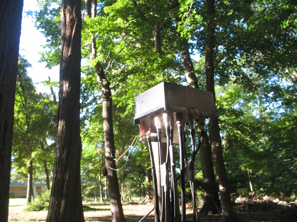
My antennas are about 150 feet from the house, but easily selected using a remote, 8 position antenna coaxial switch box.
Conclusion:
My nested loop array is working super on all five bands! There doesn't appear to be any problem of interaction of the antenna elements and the signal reports are very encouraging! It radiates most of its signal broadside to the plane, so orient it for your two most desired directions.
If you want very good on the air performance with a neighborhood friendly antenna array, this full wave loop in the vertical plane is the best option I've found so far. You can build a single loop for your favorite band, or nest multiple loops like I did. In fact, you can even add 6 and 2 meters if you like! This antenna is inexpensive, easy to build and will give you a solid signal that will be well heard!
Nested Loop Antennas - Nested Delta Loops Without Any PVC Support!
The three, nested delta loops for 20, 15 and 10 meters hang beautifully with one overhead support and just one guy on each corner!
Over time, the horizontal supporting piece of PVC in my 5 band nested loop array (detailed above) began to bow in like a kite. The array still had a good SWR and seemed to work fine, but the larger the interior of a loop, the more gain it will have, so I knew I was losing some good RF radiation in its present state. Using just 100 watts and wires to compete with folks running beams and much higher power levels, every DB of gain matters! My son Brad, KB3MNE, good friend Dave, N3HCN and I decided to put our heads together and see if we could come up with a better approach.
We decided to forgo the PVC structure entirely and simply erect the entire nested loop array with guy lines. With only one support at the top, this necessitated that we change from the square pattern we had been using (detailed above) and put up triangular shaped Delta Loops instead. This reduces the interior area and therefore theoretical gain from a square somewhat, but we suspected we could maintain a pretty good triangular shape with this approach, eliminating bowing and therefore increase the interior area over the “square” I was actually experiencing with my bowed installation.
My existing loop was set up with 5 bands - 20, 17, 15, 12 and 10, but since the wires are closer together in a triangular configuration and will only be controlled by one overhead support and two guy lines, we decided to just go with 3 bands, 20, 15 and 10, to increase our odds of success.
With a plan in place, we began construction. The wire and matching coax lengths are identical to what I’ve documented in the design above.
Relevant sections of the same chart above, repeated here for easy reference. Ignore 12 and 17 meters.
The steps and parts lists are also similar, except that you can skip anything related to the PVC, 12 and 17 meters. The only other difference is that we moved the SO 239 dipole connectors to the corner so that the radiation take off angle would be as low as possible with the triangular design. We want to work DX, not burn clouds!
Moving the connectors to the corners is good for DX, but placing the them horizontally, just before the corner, would let the coax hang better.
The main trick to easily making multiple nested delta loops cooperate and stay aligned with only one top support and one guy at each bottom corner is to first lay the entire structure out on the ground and stake the corners of all three elements so that they are all taught. Then just tie one element to the next. When you pull it up in the air it will align beautifully! In addition, this design is even stealthier than the PVC version!
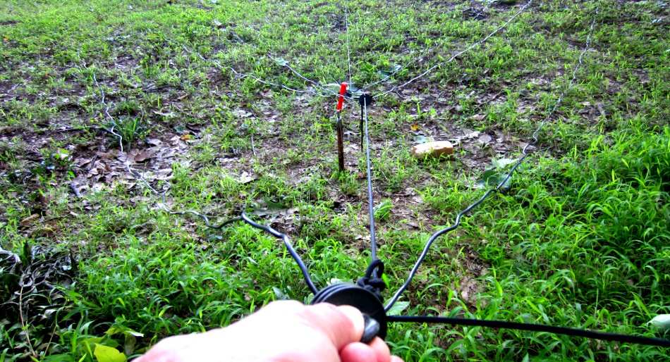
Staking the corners on the ground makes it very easy to tie off everything at the proper length.
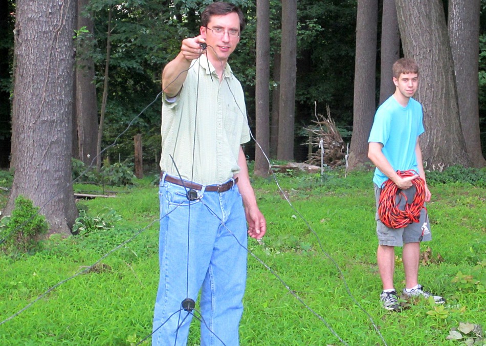
Dave, N3HCN holds the right corner insulator, to which all three antennas are attached to the right corner guy line.
Summary:
Overall, I believe this design is a very good enhancement over the original, PVC version. It is much lighter, stealthier, cheaper and a good, true triangle shape is easy to maintain. Sacrificing wires for 17 and 12 meters was not a problem; since my Icom 756 Pro II’s internal automatic antenna tuner will easily tune the adjacent loop for those bands. It may be possible to fit those loops in as well if you want to give it a try.
In terms of performance, since I replaced the original square PVC design with this one, I can't do direct A / B comparisons. Theoretically, a good square should have slightly more gain, but I can’t detect any drop off in performance with my new, nested delta loop design. With 100 watts I can easily maintain QSO rates well above 30 / HR during active contests (at times much higher) and I’m usually successful in pile ups! The loops will have a null off the ends, so orient them for you favored directions. If you want to control the direction of your signal, you can learn how I do that here!
Two important safety tips and a disclaimer: First, contact with overhead power lines can kill you! Always be mindful of the location of your power lines, your ladders, handling antennas, other metallic objects, etc. Second, you should always evaluate the placement of your antennas and address any RF exposure risks as detailed here. Any actions that you take based upon the information presented here shall be solely at your own risk. Neither N3FJP Software, our employees or any of our contributors shall be held liable for any actions taken based upon the information presented on this website.
![]()
Copyright 1997-2014, N3FJP Software - Affirmatech, Inc